»» Selengkapnya...
Kamis, 25 November 2010
Maintenance
| Tune Up Maintenance |
- Which Engine Sensors Are the Most Important?
- What Should a Complete Tune-up Include?
- What Kind of Fuel Hose Is Best?
- What Causes Spark Knock and How Do You Get Rid of It?
- What Are the Recommendations for Changing Filters?
- How Does the Oxygen Sensor Work?
- How Do You Know When a Sensor Needs to Be Replaced?
- Do Engines With Distributorless Ignitions Need Tune-ups?
- The Difference Between Throttle Body and Mulit-point Fuel Injection Systems
- Why Are There Many Different Types of Spark Plugs?
- Is It Better to Rebuild or Replace a Carburetor or Throttle Body?
- Is It Better to Clean or Replace Dirty Fuel Injectors?
- Basic Emission System Operation
Which Engine Sensors Are the Most Important?
 All sensors are important. The computer is the brains of a computerized engine control system and sensors are its link to what's happening under the hood.
The coolant sensor is often called the master sensor because the computer uses its input to regulate many other functions, including:
- Activating and deactivating the Early Fuel Evaporation (EFE) system such as the electric heating grid under carburetor or the thermactor air system.
- Open/closed loop feedback control of the air/fuel mixture. The system won't go into closed loop until the engine is warm.
- Start up fuel enrichment on fuel-injected engines, which the computer varies according to whether the engine is warm or cold.
- Spark advance and retard. Spark advance is often limited until the engine reaches normal operating temperature.
- EGR flow, which is blocked while the engine is cold to improve driveability. Canister purge, which does not occur until the engine is warm.
- Throttle kicker or idle speed.
- Transmission torque converter clutch lockup.
 The coolant sensor is usually located on the head or intake manifold where it screws into the water jacket. Sensors come in two basic varieties: variable resistor sensors called thermistors because their electrical resistance changes with temperature, and on/off switches, which work like a conventional temperature sending unit or electric cooling fan thermostat by closing or opening at a preset temperature.
Variable resistor coolant sensors provide the computer with a more accurate indication of actual engine temperature than a simple temperature switch. The computer feeds the sensor a fixed reference voltage of about five volts when the key is on.
The resistance in the sensor is high when cold and drops about 300 ohms for every degree Fahrenheit as the sensor warms up. This alters the return voltage signal back to the computer which the computer then reads to determine engine temperature.
The switch-type sensor may be designed to remain closed within a certain temperature range, or to open only when the engine is warm. Switch-type coolant sensors can be found on GM "T" car minimum function systems, Ford MCU, and Chrysler Lean Burn systems.
Because of the coolant sensor's central role in triggering many engine functions, a faulty sensor (or sensor circuit) can cause a variety of cold performance problems. The most common symptom is failure of the system to go into closed loop once the engine is warm. Other symptoms include poor cold idle, stalling, cold hesitation or stumble, and/or poor fuel mileage.
The oxygen sensor (O2) measures how much unburned oxygen is in the exhaust. The computer uses this as an indication of how rich or lean the fuel mixture is so adjustments can be made to keep it properly balanced.
A problem with the O2 sensor will prevent the computer from keeping the fuel mixture balanced under changing driving conditions, allowing the mixture to run rich or lean.
The throttle position sensor (TPS) is used with feedback carburetion and electronic fuel injection (EFI) to inform the computer about the rate of throttle opening and relative throttle position. A separate idle switch and/or wide open throttle (WOT) switch may also be used to signal the computer when these throttle positions exist.
The throttle position sensor may be mounted externally on the throttle shaft (the case on most fuel injection throttle bodies), or internally in the carburetor (as in Rochester Varajet, Dualjet and Quadrajet).
The TPS is essentially a variable resistor that changes resistance as the throttle opens. It is the electronic equivalent of a mechanical accelerator pump. By signaling the computer when the throttle opens, the computer enriches the fuel mixture to maintain proper air/fuel ratio.
Initial TPS setting is critical because the voltage signal the computer receives tells it the exact position of the throttle. Initial adjustment must be set as close as possible to factory specs. Most specs are given to the nearest hundredth of a volt.
The classic symptom of a defective or misadjusted TPS is hesitation or stumble during acceleration. The fuel mixture leans out because the computer doesn't receive the right signal telling it to add fuel as the throttle opens. The oxygen sensor feedback circuit will eventually provide the necessary information, but not quickly enough to prevent the engine from stumbling.
When the sensor is replaced, it must be adjusted to the specified reference voltage. The TPS on most remanufactured carburetors is preset at the factory to an average setting for the majority of applications the carburetor fits. Even so, the TPS should be reset to the specific application upon which it is installed.
 The manifold air pressure (MAP) sensor function is to sense air pressure or vacuum in the intake manifold. The computer uses this input as an indication of engine load when adjusting air/fuel mixture and spark timing. Computerized engine control systems that do not use a MAP sensor rely on throttle position and air sensor input to determine engine load.
Under low-load, high-vacuum conditions, the computer leans the fuel mixture and advances spark timing for better fuel economy. Under high-load, low-vacuum conditions (turbo boost, for example), the computer enriches the fuel mixture and retards timing to prevent detonation. The MAP sensor serves as the electronic equivalent of both a distributor vacuum advance diaphragm and a carburetor power valve.
The MAP sensor reads vacuum and pressure through a hose connected to the intake manifold. A pressure sensitive ceramic or silicon element and electronic circuit in the sensor generates a voltage signal that changes in direct proportion to pressure.
MAP sensors should not be confused with VAC (Vacuum) sensors, DPS (Differential Pressure sensors), or BARO or BP (Barometric Pressure) sensors. A vacuum sensor (same as a differential pressure sensor) reads the difference between manifold vacuum and atmospheric pressure (the difference in air pressure above and below the throttle plate). A VAC sensor is sometimes used instead of a MAP sensor to sense engine load.
A MAP sensor measures manifold air pressure against a pre-calibrated absolute (reference) pressure. What's the difference? A vacuum sensor only reads the difference in pressure, not absolute pressure, so it doesn't take into account changes in barometric (atmospheric) pressure.
A separate BARO sensor is usually needed with a vacuum sensor to compensate for changes in altitude and barometric pressure. Some early Ford EEC-III and EEC-IV systems have a combination barometric pressure/MAP sensor called a BMAP sensor, combining both functions. Anything interfering with accurate sensor input can upset both fuel mixture and ignition timing. Problems with the MAP sensor itself, grounds or opens in the sensor wiring circuit, and/or vacuum leaks in the intake manifold.
Typical driveability symptoms include detonation due to too much spark advance and a lean fuel ratio, and loss of power and/or fuel economy due to retarded timing and an excessively rich fuel ratio.
A vacuum leak can cause a MAP sensor to indicate low manifold vacuum, causing the computer to think the engine is under more load than it really is. Consequently, timing is retarded and the fuel mixture is enriched.
Return to top.
What Should a Complete Tune-up Include?
Electronic ignition, computerized engine controls, and electronic fuel injection have eliminated many adjustments that were once part of a "traditional" tune-up. Most would agree that a tune-up today is a preventive maintenance service and engine performance check.
Call it what you will, a complete tune-up should combine elements of preventive maintenance, adjustment and performance analysis. One of the main reasons people bring a vehicle in for a tune-up is because they are experiencing some kind of driveability problem.Things like hard starting, stalling, hesitation, misfiring, poor fuel economy, or lack of power are seldom cured by a new set of spark plugs and a few turns of a screwdriver. Every tune-up should include a comprehensive performance check to verify that no driveability problems or trouble codes exist.
Another item that should be included is an emissions check. Thirty-five states now have some type of annual vehicle emissions inspection program, and all but two include a tailpipe emissions check. Most mechanics will check EGR valve operation, the PCV valve, and make a visual inspection of other emission control components and plumbing. But unless an actual emissions performance check is made at the tailpipe, there is no way to know whether or not the vehicle will meet applicable emission standards. An emissions check is a must.
Taking into account longer service intervals and reduced maintenance requirements of today's vehicles, a tune-up is probably only necessary every 30,000 miles, or once every two to three years. This is altered when a driveability or emissions problem arises that requires diagnosis and repair.
The best guide to tune-up frequency is probably the recommended spark plug replacement interval in a vehicle's owners manual.
Our list of items that should be included in a "complete" tune-up include:
- Replace spark plugs
- Replace rotor
- Check distributor cap (replace if necessary)
- Check timing (adjust if necessary)
- Check ignition wires (replace if necessary)
- Check ignition performance (firing voltage and ignition patterns)
- Check idle speed (adjust if necessary)
- Check choke (carbureted engines)
- Clean fuel injectors
- Check compression and/or power balance (identifies bad fuel injectors as well as compression problems)
- Check manifold intake vacuum (reveals exhaust restrictions)
- Check battery/charging voltage
- Check exhaust emissions (verifies fuel mixture, ignition performance and emissions performance)
- Check vehicle computer for trouble codes
- Install new air filter
- Replace fuel filter
- Replace PCV valve
- Check all emission controls (EGR valve, air pump, etc.)
- Check all vital fluid levels (engine oil, transmission fluid, coolant, brakes, power steering)
- Check belts and hoses
- Check safety items such as lights, wipers, tires (including inflation pressure), horn, etc.
What Kind of Fuel Hose Is Best?
Fuel, emissions and vacuum hoses are made of special materials to handle the liquids and vapors they carry. Fuel hose, for example, is made to withstand gasoline and alcohol (up to a certain percentage concentration). It is also reinforced to withstand internal pressure.
It is extremely important not to use any other type of hose for a fuel line. Use only approved fuel hose that is rated for carrying gasoline.It is also extremely important to use hose with the correct pressure rating for the application. Hose for electronic fuel injection (EFI) must have a higher pressure rating (35 - 70 psi or higher) than that approved for carbureted engines (7 - 10 psi).
You can always use higher rated EFI hose on a carbureted application, but never the reverse. If lower pressure carburetor fuel hose is used on a high pressure EFI engine, it may burst and cause a fire.
High pressure EFI hoses often require special high pressure rolled-edge clamps rather than standard clamps or spring clamps. Some EFI hose also uses special connectors. Ford and Mercury fuel injected engines, for example, have hard nylon fuel lines held in place by push connectors.
Return to top.
What Causes Spark Knock and How Do You Get Rid of It?
 The left side of drawing shows completion of normal combustion. The right side shows a detonating cylinder, where the last portion of the air/fuel mixture self-ignites and collides with the normal combustion front.
Instead of a single flame front growing outward smoothly like an expanding balloon from the point of ignition, multiple flame fronts are generated spontaneously throughout the combustion chamber as the fuel automatically ignites from heat and pressure. The multiple flame fronts collide, creating shock waves that produce a sharp metallic pinging or knocking noise.
Mild detonation can occur in almost any engine and will not cause damage. Prolonged heavy detonation can crack pistons and rings, blow out head gaskets, damage spark plugs and valves, and flatten rod bearings.
Any of the following can cause detonation:
- Too Much Compression: An accumulation of carbon deposits in the combustion chambers, on piston tops and valves can increase compression to the point where it exceeds fuel octane rating. If a top cleaner fuel additive fails to remove deposits, a new alternative is to blast the deposits loose by blowing crushed walnut shells through the spark plug hole. Otherwise, the head will have to be removed so the deposits can be scraped off.
- Overadvanced Ignition Timing: Too much spark advance causes cylinder pressure to rise too rapidly. If resetting the timing to stock specifications does not help, retarding timing a couple of degrees may be necessary to eliminate knock.
- Engine Overheating: A hot engine is more likely to suffer spark knock than one which runs at normal temperature. Overheating can be caused by low coolant, a defective fan clutch, too hot a thermostat, a bad water pump, etc. A buildup of lime and rust deposits in the head and block can also reduce heat transfer.
- Overheated Air: The thermostatically controlled air cleaner provides the carburetor with hot air to aid fuel vaporization during engine warm-up. If the air control door sticks shut so that the carburetor continues to receive heated air after the engine is warm, detonation may occur, especially during hot weather. Check the operation of the air flow control door in the air cleaner to see that it opens as the engine warms up. No movement may mean a loose vacuum hose or a defective vacuum motor or thermostat.
- Lean Fuel Mixture: Rich fuel mixtures resist detonation while lean ones do not. Air leaks in vacuum lines, intake manifold gaskets, carburetor gaskets or fuel injection intake plumbing downstream of the throttle can all admit extra air into the engine and lean out the fuel mixture. Lean mixtures can also be caused by dirty fuel injectors, carburetor jets clogged with fuel deposits or dirt, a restricted fuel filter, or a weak fuel pump. The air/fuel ratio can also be affected by changes in altitude. A carburetor calibrated for high altitude driving will run too lean if driven at a lower elevation. Altitude changes are generally compensated for on computer cars by the barometric pressure. A lean fuel condition can be diagnosed by watching for lean misfire on an ignition scope, or by using a four-gas infrared analyzer and watching exhaust oxygen levels. A reading over about 3% to 4% oxygen would indicate a lean fuel condition.
- Spark Plug Too Hot: The wrong heat range plug can cause detonation as well as pre-ignition. Copper core plugs are less likely to cause detonation than standard spark plugs.
- Loss of Exhaust Gas Recirculation (EGR): EGR keeps combustion temperatures down, reducing the tendency to detonate. If the EGR valve is inoperative or someone has disconnected or plugged its vacuum hose, higher combustion temperatures can cause pinging.
- Low Octane Fuel: Burning cheap gas may be one way to save pennies, but switching to a higher grade of fuel may be necessary to eliminate a persistent knock problem.
- Defective Knock Sensor: The knock sensor responds to frequency vibrations produced by detonation (typically 6 - 8 kHz), and signals the computer to momentarily retard ignition timing until detonation stops. A knock sensor can usually be tested by rapping a wrench on the manifold near the sensor (never hit the sensor itself). If there is no timing retard, the sensor may be defective.
What Are the Recommendations for Changing Filters?
It is best to follow the Severe Service maintenance schedules found in most new car owner's manuals, with a few exceptions:
 The oxygen (O2) sensor is the only sensor that makes its own voltage. The voltage signal is proportional to the amount of unburned oxygen in the exhaust. When hot (at least 600° F), the zirconium dioxide element in the sensor's tip produces a voltage signal that varies according to the difference in oxygen content between exhaust and outside air.The higher the concentration of unburned oxygen in the exhaust, the lower the differential across the sensor tip and the lower the sensor's voltage output. The sensor's output ranges from 0.1 volts (lean) to 0.9 volts (rich). A perfectly balanced (stoichiometric) fuel mixture of 14.7:1, gives a reading of around 0.5 volts.
Some O2 sensors have three wires and an internal heating element to help the sensor reach operating temperature more quickly. The heater also keeps the sensor from cooling off when the engine is idling.
 An O2 sensor's normal life span is about 30,000 to 50,000 miles. Sensors can fail prematurely if they become clogged with carbon, or are contaminated by lead from leaded gasoline or solvents from the wrong type of RTV silicone sealer.As the sensor ages, it becomes sluggish. When the signal starts to lag behind changes in the exhaust, or becomes static, the engine experiences driveability problems (loss of power, rough idle, poor fuel mileage, or excessive emissions).
The engine computer supplies a base reference voltage of approximately one volt to the titania O2 sensor, and then reads the voltage flowing through the sensor to monitor the air/fuel ratio.
When the fuel mixture is rich, resistance in a titania sensor will be low so the voltage signal will be high (close to 1.0 volt). When the fuel mixture is lean, resistance increases and the voltage signal drops down to about 0.1 volt.
Compared to the more common zirconia O2 sensors, titania sensors have three advantages:
Return to top.
The latter is the preferred technique because it also allows you to read sensor voltages and inputs directly on most GM and some Ford and Chrysler systems.
A trouble code does not necessarily mean a sensor is bad. However. It only means a problem has been detected in a particular sensor circuit. It could be the sensor, the wiring, or a connector somewhere in the wiring harness.
To isolate the fault, a series of diagnostic tests usually have to be performed, following a step-by-step procedure. Tests may require the use of a breakout box that allows individual circuits to be tested. By checking continuity, resistance and/or voltage readings, the faulty component can be isolated.
Another approach is to use a tester that simulates voltage, resistance or frequency inputs from various sensors. The tester is used in place of a sensor to produce a substitute signal. If the on-board computer then responds properly, the sensor is assumed to be faulty.
Intermittent faults are the hardest to find, and some sensor problems may not generate a trouble code at all. A technician may have to test drive the car with a portable "flight recorder" plugged into the on-board computer system in order to locate the problem. When the problem occurs, pressing a button records the various sensor readings for later analysis.
Return to top.
Distributorless systems eliminate the need for distributor-related maintenance, but do not diminish the need for other maintenance such as replacing the PCV valve, fuel filter, air filter, etc.
Return to top.
 Fuel metering in both types of EFI systems is controlled by a combination of fuel pressure and injector timing. The longer injectors are on, the greater volume of fuel delivered to the engine.Fuel delivery is also increased when there is a greater pressure differential between intake vacuum and fuel line pressure (which is controlled by a fuel pressure regulator).
Some of the other components in both types of EFI systems with which you should be familiar include:
Idle Air Control (IAC) Valve - used on EFI applications for idle speed control. The electric motor opens and closes a valve so air can bypass the throttle plates. Failure may cause stalling.
Throttle Position Sensor (TPS) - A rheostat-like device that mounts on the throttle shaft to inform the computer about throttle opening. Failure may cause hesitation. Sensor must be carefully adjusted when installed to give an accurate voltage reading.
Airflow Sensor - Used to measure how much air is entering the engine so the appropriate amount of fuel can be delivered through the injectors. Basic types include the "flap" style used on many import and domestic Bosch systems, and the "heated filament" and "hot wire" mass airflow sensors. Expensive to replace.
Cold Start Valve - An auxiliary fuel injector that provides extra fuel enrichment when a cold engine is first started. If defective, can cause hard starting. If leaks, can cause rich fuel mixture.
Warm-up Regulators - a device that controls fuel enrichment during engine warm-up on Bosch CIS fuel injection systems.
Fuel Pressure Regulator - A spring-loaded diaphragm that is used in EFI systems to control fuel pressure. Rebuild kits are available for certain applications.
Fuel Injector - Two types: mechanical and electronic. Mechanical injectors are used in Bosch CIS/K-Jetronic import applications, while electronic injectors are used on all domestic EFI applications. The electronic variety contains a solenoid that lifts a pintle valve open so fuel can spray out of the injector. The mechanical variety is spring loaded and calibrated to open when a certain minimum pressure is achieved. Both are susceptible to clogging from dirt and fuel residue. One new type of replacement injector has a disc valve design that resists clogging.
Return to top.
The center electrode runs much hotter than the side electrode because the center electrode is encased in ceramic (a good insulator of heat as well as electricity). This slows down heat transfer from center electrode to cylinder head.
If ignition polarity is reversed, it can take up to 40% more firing voltage to send the spark from ground electrode to center electrode. The result can be misfiring under load and poor engine performance.
Keeping the center electrode hot also helps burn off fuel and oil deposits that form on the insulator tip. Deposits can conduct voltage away from the gap causing the plug to misfire, so keeping the center electrode hot helps prevent fouling.
If the plug is too hot for the application, it can become a source of pre-ignition. If the plug is too cold, it can experience fouling problems.
The operating temperature of a spark plug depends on a number of variables. The two most influential are cylinder head temperature and the relative richness or leanness of the fuel mixture. Given such variables, it is impossible to have a single spark plug that would work well in every application, even if thread sizes and reach were standardized. Heat range is determined by several design features, one of which is the distance heat must travel from center electrode tip to the plug's shell. A plug with a short ceramic insulator between electrode tip and shell runs cooler than one with a long nose insulator.
A cold plug is good for high speed, high load operation because it sheds heat quickly and is less likely to overheat and cause pre-ignition. Colder heat ranges are used most often in high performance and turbocharged engines.
For short-trip, stop-and-go driving, a cold plug may not run hot enough to keep itself clean. A hotter heat range plug may be needed to resist fouling.
For sustained high speed or high load running, a hotter plug may become too hot and cause preignition. The trick is to use a plug hot enough to prevent fouling yet cold enough so there is no danger of pre-ignition.
One way to extend or broaden the heat range of a spark plug is to extend the tip of the plug further into the combustion chamber. The longer insulator makes the tip run hotter for better self-cleaning at low speeds and light loads. It also exposes the tip to more of the incoming air/fuel mixture, keeping it from overheating at high speeds and loads. An extended tip spark plug typically has a much broader heat range than a standard spark plug.
Another way to increase heat range is to use a center electrode with a copper core. Copper is an excellent conductor of both heat and electricity. With a copper core center electrode, heat is carried away from the plug tip through the electrode during high speed, high load operation. This allows the plug to dissipate heat more quickly like a colder plug, yet stay hot enough to burn off fouling deposits.
Because of the increased heat range copper core plugs offer, one plug can be used in applications formerly requiring several different plugs with narrower heat ranges. The use of a platinum or gold palladium center electrode is another design innovation that improves fouling resistance while greatly extending plug life. The special alloy at the tip of the center electrode is more wear and corrosion resistant than standard electrode metal. It allows the use of a longer insulator, helping plugs reach a self-cleaning temperature of 750° F in only a few seconds.
Spark plug manufacturers avoid making specific mileage claims for such premium plugs, but many experts say the plugs will often last up to 60,000 miles. Other benefits include better cold starting, less cold fouling, and improved operation during both stop-and-go and highway driving. These plugs are considerably more expensive than standard plugs.
Return to top.
 If all the carburetor needs is cleaning and adjusting, then a kit will usually do the trick. A kit is also an option if the carburetor needs a gasket, diaphragm, needle valve, check valve, or other component commonly included in a kit.Floats, choke housings and choke pulloffs are usually sold separately, but are relatively easy to replace if defective. Faulty or misadjusted chokes and floats probably account for more carburetor problems than anything else.
Most carburetors today have molded foam floats rather than hollow brass floats. Some import carbs have hollow plastic floats. If a hollow float develops a leak, it will fill with fuel and sink, causing the carburetor to flood.
The solid foam variety can absorb fuel over a period of time. That's why the float should always be weighed when the carburetor is rebuilt. A heavy float will make the fuel mixture rich. Replace heavy floats.
 Kits are not for everyone. It takes a fair amount of know-how to properly rebuild and adjust a carburetor. It also takes a lot of time to disassemble, clean, inspect, and reassemble a carburetor. Many professional installers, as well as do-it-yourselfers, prefer to replace a troublesome carburetor rather than to try to rebuild it with a kit.
There are some carburetor problems that cannot be fixed by a kit or by replacing faulty components. Wear around throttle shafts or warpage in the carburetor body or throttle plate can create vacuum leaks that foul up fuel metering. The only option here is replacement.
Most rebuilt carburetors are sold on an exchange basis, so it's important to make sure that the exchange carburetor is complete (all external parts intact), has not been disassembled, and is correct for the application.
If a base gasket is not included with the replacement, be sure your customer gets one before he leaves. Your customer may also need new fuel hose, fuel filter, and air filter to complete the installation.
 Injectors include a precision-ground needle valve and are controlled by an electro-magnetic solenoid that is turned on and off by an electric control unit. Fuel is injected only during the "on" time and is metered by the size of the opening, duration of "on" time, and fuel pressure.
Every time the injector sprays fuel, a small amount remains in the nozzle. As it evaporates, it leaves behind a wax-like residue that forms hard varnish deposits.
The rate at which deposits build up depends on the quality of gasoline burned, whether or not the gas has detergent in it (and what kind), and the number of thermal cycles the engine experiences per miles driven. Short-trip driving builds up deposits more quickly than continuous driving.
As deposits build up in injectors, they restrict the discharge orifice and break up the normal cone-shaped spray pattern. The spray pattern may develop "legs" (streamers of unatomized fuel) or turn into a continuous stream of unatomized fuel like a fire hose.
Liquid fuel does not burn as efficiently as atomized fuel, so it has a "leaning effect" on the air/fuel mixture. Accumulated deposits in the discharge orifice also restrict the total amount of fuel delivered per squirt, which further compounds the leaning effect. This can result in the appearance of driveability problems such as hard starting, hesitation, poor fuel economy, loss of power, and elevated exhaust emissions.
An engine with dirty injectors will usually show a wide variation in RPM between cylinders when doing a power balance test. There will also be a lot of variation in peak firing voltages between cylinders on a scope.
When the engine is started, the solvent becomes the temporary "fuel supply" while injectors are cleaned.
Off-car cleaning involves more work, but results are often worth it. For one thing, injectors that don't respond to on-car cleaning can often be restored to like-new performance with off-car cleaning.
Some available cleaning equipment can reverse flush injectors, doing a thorough cleaning job. Most off-car cleaning equipment also allows the mechanic to observe and measure injector flow patterns so bad ones can be identified.
Flow rating also allows injectors to be more closely matched for improved engine performance.
Return to top.
 Crankcase blowby vapors are eliminated as a source of pollution by recirculating the vapors into the engine for reburning through the Positive Crankcase Ventilation (PCV) system.
The PCV valve acts like a small calibrated vacuum leak, allowing manifold vacuum to siphon air through the crankcase, taking with it moisture and blowby gases that would otherwise pollute the atmosphere. As a side benefit, it extends motor oil life.
 Evaporative emissions are eliminated by sealing the fuel system and storing vapors in a charcoal canister. When the engine starts, a purge valve on the canister opens, allowing manifold vacuum to siphon vapors into the intake manifold to be burned in the engine.
There are 3 primary tail pipe pollutants:
Carbon monoxide is the worst pollutant of the three because it is deadly. CO emissions are reduced by keeping the air/fuel ratio lean, by preheating incoming air and manifold to aid fuel vaporization, and by converting the remaining CO into harmless carbon dioxide in the catalytic converter.
Hydrocarbon (HC) emissions are unburned gasoline. HC is not directly harmful, but it contributes to smog formation. A fouled spark plug, a leaky exhaust valve, or a fuel mixture so lean it won't ignite (lean misfire) can all allow unburned fuel to enter the exhaust.
HC is reduced by maintaining a balanced air/fuel mixture, by making sure compression and ignition are OK, and by reburning any HC remaining in the catalytic converter.
Nitrogen Oxides (NOX) are formed in the combustion chamber when temperatures rise above 2,500° F and nitrogen begins to react with oxygen. Lean air/fuel mixtures burn hotter and increase NOX.
Though not as poisonous as carbon monoxide, NOX irritates the eyes, nose and lungs, and contributes to ozone depletion and acid rain formation.
Return to top.

- Air filters need to be inspected regularly and replaced as often as needed, regardless of mileage or time. Dirty air filters can increase fuel consumption and exhaust emissions.
- Fuel filters should be replaced yearly and/or at every tune-up, especially on fuel injected cars. The fuel filter in a vehicle with electronic fuel injection passes a much larger volume of fuel than its counterpart in a carbureted application. If the tank is dirty or rusty, constant fuel recirculation can pick up a lot of debris that ends up in the filter. If the filter plugs, the engine is starved for fuel or unfiltered fuel is allowed to bypass the filter. The latter can damage injectors.
- Oil filters need to be replaced at every oil change (every six months or 3,000 miles in most cases) despite the advice in many owner's manuals to only change the filter at every other oil change. A new filter is cheap insurance against major engine damage, so why take unnecessary risks?
- Automatic Transmission Fluid Filter - Few owner's manuals have a suggested change interval for the automatic transmission fluid (ATF) or fluid filter unless the vehicle is used for towing. Most transmission specialists say the best preventative maintenance for prolonging automatic transmission life is to change fluid and filter every two years or 30,000 miles.
Follow the manufacturer's recommendations on the specific type of ATF to use. The type of ATF should match the specs required for the application.
All GMs, most late model Chryslers and many imports use Dexron II. All 1988 and later Fords require Mercon ATF. Most universal ATF fluids are acceptable for either of these. Older Fords or imports require Type F fluid.
How Does the Oxygen Sensor Work?
The oxygen (O2) sensor is the only sensor that makes its own voltage. The voltage signal is proportional to the amount of unburned oxygen in the exhaust. When hot (at least 600° F), the zirconium dioxide element in the sensor's tip produces a voltage signal that varies according to the difference in oxygen content between exhaust and outside air.Some O2 sensors have three wires and an internal heating element to help the sensor reach operating temperature more quickly. The heater also keeps the sensor from cooling off when the engine is idling.
Sensor Life Span
An O2 sensor's normal life span is about 30,000 to 50,000 miles. Sensors can fail prematurely if they become clogged with carbon, or are contaminated by lead from leaded gasoline or solvents from the wrong type of RTV silicone sealer.Sensor Accuracy
Sensor accuracy can also be affected by air leaks in the intake or exhaust manifold, or even a fouled spark plug. A misfiring plug allows unburned oxygen to pass through into the exhaust, causing the O2 sensor to give a false lean indication.
After Market Sensors
Most aftermarket replacement oxygen sensors are of a universal design which means some wire splicing may be necessary during installation. Graphite anti-seize compound should be used on sensor threads unless they are precoated. The rubber boot that fits over the sensor should not be pushed down further than half an inch from the sensor's base.
Some vehicles are equipped with a different type of O2 sensor that has a titania rather than zirconia element. Instead of generating its own voltage signal, a titania O2 sensor changes resistance as the air/fuel ratio goes from rich to lean. Instead of a gradual change, it switches from low resistance (less than 1,000 ohms) when the mixture is rich, to high resistance (over 20,000 ohms) when the mixture is lean.The engine computer supplies a base reference voltage of approximately one volt to the titania O2 sensor, and then reads the voltage flowing through the sensor to monitor the air/fuel ratio.
When the fuel mixture is rich, resistance in a titania sensor will be low so the voltage signal will be high (close to 1.0 volt). When the fuel mixture is lean, resistance increases and the voltage signal drops down to about 0.1 volt.
Compared to the more common zirconia O2 sensors, titania sensors have three advantages:
- they don't need an air reference (there is no internal venting to the outside atmosphere to plug up)
- they have a fast warm-up time (about 15 seconds) and
- they work at lower exhaust temperatures (they won't cool off at idle and they can be located further downstream from the engine or used with turbochargers)
Return to top.
How Do You Know When a Sensor Needs to Be Replaced?
The vehicle will usually exhibit a driveability problem (hard starting, stalling, hesitation, poor mileage, high emissions, etc.) and/or an illuminated check engine light. Many things other than a bad sensor can cause driveability problems, but a check engine light is a good indication that the problem is in the electronics.
Mileage is another consideration. The oxygen sensor should go 50,000 miles or more, but some fail in as little as 30,000 miles. Other sensors should last the life of the vehicle. All are covered under the vehicle manufacturer's five year/50,000 miles emissions warranty. Troubleshooting sensor problems requires checking the on-board diagnostics to see if the computer has set a trouble code (see chart) corresponding to one of the sensor circuits. This is done by either putting the computer into a special diagnostic mode and counting check engine "flashes" or special diagnostic LEDs on the computer itself (many import applications), or by plugging a special scan tool into the diagnostic connector to access on-board diagnostics.The latter is the preferred technique because it also allows you to read sensor voltages and inputs directly on most GM and some Ford and Chrysler systems.
A trouble code does not necessarily mean a sensor is bad. However. It only means a problem has been detected in a particular sensor circuit. It could be the sensor, the wiring, or a connector somewhere in the wiring harness.
To isolate the fault, a series of diagnostic tests usually have to be performed, following a step-by-step procedure. Tests may require the use of a breakout box that allows individual circuits to be tested. By checking continuity, resistance and/or voltage readings, the faulty component can be isolated.
Another approach is to use a tester that simulates voltage, resistance or frequency inputs from various sensors. The tester is used in place of a sensor to produce a substitute signal. If the on-board computer then responds properly, the sensor is assumed to be faulty.
Intermittent faults are the hardest to find, and some sensor problems may not generate a trouble code at all. A technician may have to test drive the car with a portable "flight recorder" plugged into the on-board computer system in order to locate the problem. When the problem occurs, pressing a button records the various sensor readings for later analysis.
Return to top.
Do Engines With Distributorless Ignitions Need Tune-ups?
Yes, but there is not as much to "tune." Timing is not adjustable on most applications, and there is no distributor cap or rotor to wear out or replace.
Even so, the engine will need new spark plugs every 30,000 miles. When plugs are replaced, the ignition system should be checked to verify its overall performance. Plug wires deteriorate over time, coils get weak and sensor problems can arise.Distributorless systems eliminate the need for distributor-related maintenance, but do not diminish the need for other maintenance such as replacing the PCV valve, fuel filter, air filter, etc.
Return to top.
The Difference Between Throttle Body and Mulit-point Fuel Injection Systems
| The two basic types of electronic fuel injection (EFI) in use today are Throttle Body Injection (TBI) and Multi-Point Injection (MPI). Throttle Body Injection A TBI system is similar to a carburetor in that one or two injectors are located in a central throttle body that supplies fuel to the engine through the intake manifold. Instead of using engine vacuum to siphon fuel through metering circuits as a carburetor does, fuel is sprayed into the manifold through the injectors. |
Multi-point Injection  In a MPI system, each cylinder has its own individual injector. The injectors are mounted at each of the intake ports so fuel can be sprayed directly into the ports. A single throttle body meters the amount of air entering the intake manifold so the amount of fuel delivered can be matched to the engine's needs. In a MPI system, each cylinder has its own individual injector. The injectors are mounted at each of the intake ports so fuel can be sprayed directly into the ports. A single throttle body meters the amount of air entering the intake manifold so the amount of fuel delivered can be matched to the engine's needs. |
Fuel Regulation
Fuel metering in both types of EFI systems is controlled by a combination of fuel pressure and injector timing. The longer injectors are on, the greater volume of fuel delivered to the engine.Some of the other components in both types of EFI systems with which you should be familiar include:
Idle Air Control (IAC) Valve - used on EFI applications for idle speed control. The electric motor opens and closes a valve so air can bypass the throttle plates. Failure may cause stalling.
Throttle Position Sensor (TPS) - A rheostat-like device that mounts on the throttle shaft to inform the computer about throttle opening. Failure may cause hesitation. Sensor must be carefully adjusted when installed to give an accurate voltage reading.
Airflow Sensor - Used to measure how much air is entering the engine so the appropriate amount of fuel can be delivered through the injectors. Basic types include the "flap" style used on many import and domestic Bosch systems, and the "heated filament" and "hot wire" mass airflow sensors. Expensive to replace.
Cold Start Valve - An auxiliary fuel injector that provides extra fuel enrichment when a cold engine is first started. If defective, can cause hard starting. If leaks, can cause rich fuel mixture.
Warm-up Regulators - a device that controls fuel enrichment during engine warm-up on Bosch CIS fuel injection systems.
Fuel Pressure Regulator - A spring-loaded diaphragm that is used in EFI systems to control fuel pressure. Rebuild kits are available for certain applications.
Fuel Injector - Two types: mechanical and electronic. Mechanical injectors are used in Bosch CIS/K-Jetronic import applications, while electronic injectors are used on all domestic EFI applications. The electronic variety contains a solenoid that lifts a pintle valve open so fuel can spray out of the injector. The mechanical variety is spring loaded and calibrated to open when a certain minimum pressure is achieved. Both are susceptible to clogging from dirt and fuel residue. One new type of replacement injector has a disc valve design that resists clogging.
Return to top.
Why Are There Many Different Types of Spark Plugs?
Spark plugs need 5,000 to 40,000 volts from the ignition coil before a spark will jump across its electrode gap. It takes a lot of voltage to push the spark across the gap because air doesn't conduct electricity unless it is ionized first. The spark jumps from center electrode to side ground electrode.
The reason why a plug fires from center electrode to side ground electrode, instead of vice versa, is because it's easier for a spark to originate at a hot electrode than a cooler one.The center electrode runs much hotter than the side electrode because the center electrode is encased in ceramic (a good insulator of heat as well as electricity). This slows down heat transfer from center electrode to cylinder head.
If ignition polarity is reversed, it can take up to 40% more firing voltage to send the spark from ground electrode to center electrode. The result can be misfiring under load and poor engine performance.
Keeping the center electrode hot also helps burn off fuel and oil deposits that form on the insulator tip. Deposits can conduct voltage away from the gap causing the plug to misfire, so keeping the center electrode hot helps prevent fouling.
If the plug is too hot for the application, it can become a source of pre-ignition. If the plug is too cold, it can experience fouling problems.
The operating temperature of a spark plug depends on a number of variables. The two most influential are cylinder head temperature and the relative richness or leanness of the fuel mixture. Given such variables, it is impossible to have a single spark plug that would work well in every application, even if thread sizes and reach were standardized. Heat range is determined by several design features, one of which is the distance heat must travel from center electrode tip to the plug's shell. A plug with a short ceramic insulator between electrode tip and shell runs cooler than one with a long nose insulator.
A cold plug is good for high speed, high load operation because it sheds heat quickly and is less likely to overheat and cause pre-ignition. Colder heat ranges are used most often in high performance and turbocharged engines.
For short-trip, stop-and-go driving, a cold plug may not run hot enough to keep itself clean. A hotter heat range plug may be needed to resist fouling.
For sustained high speed or high load running, a hotter plug may become too hot and cause preignition. The trick is to use a plug hot enough to prevent fouling yet cold enough so there is no danger of pre-ignition.
One way to extend or broaden the heat range of a spark plug is to extend the tip of the plug further into the combustion chamber. The longer insulator makes the tip run hotter for better self-cleaning at low speeds and light loads. It also exposes the tip to more of the incoming air/fuel mixture, keeping it from overheating at high speeds and loads. An extended tip spark plug typically has a much broader heat range than a standard spark plug.
Another way to increase heat range is to use a center electrode with a copper core. Copper is an excellent conductor of both heat and electricity. With a copper core center electrode, heat is carried away from the plug tip through the electrode during high speed, high load operation. This allows the plug to dissipate heat more quickly like a colder plug, yet stay hot enough to burn off fouling deposits.
Because of the increased heat range copper core plugs offer, one plug can be used in applications formerly requiring several different plugs with narrower heat ranges. The use of a platinum or gold palladium center electrode is another design innovation that improves fouling resistance while greatly extending plug life. The special alloy at the tip of the center electrode is more wear and corrosion resistant than standard electrode metal. It allows the use of a longer insulator, helping plugs reach a self-cleaning temperature of 750° F in only a few seconds.
Spark plug manufacturers avoid making specific mileage claims for such premium plugs, but many experts say the plugs will often last up to 60,000 miles. Other benefits include better cold starting, less cold fouling, and improved operation during both stop-and-go and highway driving. These plugs are considerably more expensive than standard plugs.
Return to top.
Is It Better to Rebuild or Replace a Carburetor or Throttle Body?
Carburator
If all the carburetor needs is cleaning and adjusting, then a kit will usually do the trick. A kit is also an option if the carburetor needs a gasket, diaphragm, needle valve, check valve, or other component commonly included in a kit.Most carburetors today have molded foam floats rather than hollow brass floats. Some import carbs have hollow plastic floats. If a hollow float develops a leak, it will fill with fuel and sink, causing the carburetor to flood.
The solid foam variety can absorb fuel over a period of time. That's why the float should always be weighed when the carburetor is rebuilt. A heavy float will make the fuel mixture rich. Replace heavy floats.
Kits are not for everyone. It takes a fair amount of know-how to properly rebuild and adjust a carburetor. It also takes a lot of time to disassemble, clean, inspect, and reassemble a carburetor. Many professional installers, as well as do-it-yourselfers, prefer to replace a troublesome carburetor rather than to try to rebuild it with a kit.There are some carburetor problems that cannot be fixed by a kit or by replacing faulty components. Wear around throttle shafts or warpage in the carburetor body or throttle plate can create vacuum leaks that foul up fuel metering. The only option here is replacement.
Most rebuilt carburetors are sold on an exchange basis, so it's important to make sure that the exchange carburetor is complete (all external parts intact), has not been disassembled, and is correct for the application.
If a base gasket is not included with the replacement, be sure your customer gets one before he leaves. Your customer may also need new fuel hose, fuel filter, and air filter to complete the installation.
Throttle Body
Because there are many small components included in a TBI kit, it is important to inspect each kit to verify that everything is included. Installers must pay close attention to the kit when assembling the unit to be sure small parts are placed in their respective positions.
Return to top.Is It Better to Clean or Replace Dirty Fuel Injectors?
Injector Operation
Injectors include a precision-ground needle valve and are controlled by an electro-magnetic solenoid that is turned on and off by an electric control unit. Fuel is injected only during the "on" time and is metered by the size of the opening, duration of "on" time, and fuel pressure.Injector Service
Try cleaning them first. If this is not successful, they must be replaced.
Why They Get Dirty
Because of their construction, fuel injectors tend to "gum up" after 15,000 to 30,000 miles of driving. Fuel spraying from the injector must pass through a very small opening in the discharge nozzle. This is necessary to create a cone-shaped spray pattern that breaks the fuel up into a fine mist for proper atomization.
Some newer style injectors are more clog resistant than their predecessors, but all are vulnerable to some extent.Every time the injector sprays fuel, a small amount remains in the nozzle. As it evaporates, it leaves behind a wax-like residue that forms hard varnish deposits.
The rate at which deposits build up depends on the quality of gasoline burned, whether or not the gas has detergent in it (and what kind), and the number of thermal cycles the engine experiences per miles driven. Short-trip driving builds up deposits more quickly than continuous driving.
As deposits build up in injectors, they restrict the discharge orifice and break up the normal cone-shaped spray pattern. The spray pattern may develop "legs" (streamers of unatomized fuel) or turn into a continuous stream of unatomized fuel like a fire hose.
Liquid fuel does not burn as efficiently as atomized fuel, so it has a "leaning effect" on the air/fuel mixture. Accumulated deposits in the discharge orifice also restrict the total amount of fuel delivered per squirt, which further compounds the leaning effect. This can result in the appearance of driveability problems such as hard starting, hesitation, poor fuel economy, loss of power, and elevated exhaust emissions.
An engine with dirty injectors will usually show a wide variation in RPM between cylinders when doing a power balance test. There will also be a lot of variation in peak firing voltages between cylinders on a scope.
Fuel Additives or Pressurized Solvents Can Help
For do-it-yourselfers, there are two options - use a fuel additive to clean the injectors, or buy a can of pressurized solvent that's designed for on-car injector cleaning. Fuel additives can only do so much, so badly-clogged injectors usually need to be pressure flushed with solvent.
With on-car cleaning, pressurized solvent is run through injectors to flush out deposits. To do this, the fuel pump is temporarily disconnected so solvent can be fed directly into the test valve fitting on the fuel rail.When the engine is started, the solvent becomes the temporary "fuel supply" while injectors are cleaned.
Removal and Cleaning Might be Necessary
The resulting improvement in performance is usually quite noticeable. But on-car cleaning doesn't always do the trick, especially if an injector is badly plugged.
Unless injectors are removed and tested, there is no easy way to spot marginal injectors (those with defective spray patterns) or ones that don't deliver as much fuel as the others (mismatched injectors can reduce horsepower and increase emissions).Off-car cleaning involves more work, but results are often worth it. For one thing, injectors that don't respond to on-car cleaning can often be restored to like-new performance with off-car cleaning.
Some available cleaning equipment can reverse flush injectors, doing a thorough cleaning job. Most off-car cleaning equipment also allows the mechanic to observe and measure injector flow patterns so bad ones can be identified.
Flow rating also allows injectors to be more closely matched for improved engine performance.
Return to top.
Basic Emission System Operation
Basic Emission Control Systems and What They Do
Automotive-generated pollutants come from three sources: tailpipe, crankcase blowby vapors and fuel vapors that evaporate from the fuel tank and carburetor.
Crankcase blowby vapors are eliminated as a source of pollution by recirculating the vapors into the engine for reburning through the Positive Crankcase Ventilation (PCV) system.The PCV valve acts like a small calibrated vacuum leak, allowing manifold vacuum to siphon air through the crankcase, taking with it moisture and blowby gases that would otherwise pollute the atmosphere. As a side benefit, it extends motor oil life.
Evaporative emissions are eliminated by sealing the fuel system and storing vapors in a charcoal canister. When the engine starts, a purge valve on the canister opens, allowing manifold vacuum to siphon vapors into the intake manifold to be burned in the engine.There are 3 primary tail pipe pollutants:
- Carbon monoxide
- Hydrocarbon
- Oxides of Nitrogen
Carbon monoxide is the worst pollutant of the three because it is deadly. CO emissions are reduced by keeping the air/fuel ratio lean, by preheating incoming air and manifold to aid fuel vaporization, and by converting the remaining CO into harmless carbon dioxide in the catalytic converter.
Hydrocarbon (HC) emissions are unburned gasoline. HC is not directly harmful, but it contributes to smog formation. A fouled spark plug, a leaky exhaust valve, or a fuel mixture so lean it won't ignite (lean misfire) can all allow unburned fuel to enter the exhaust.
HC is reduced by maintaining a balanced air/fuel mixture, by making sure compression and ignition are OK, and by reburning any HC remaining in the catalytic converter.
Nitrogen Oxides (NOX) are formed in the combustion chamber when temperatures rise above 2,500° F and nitrogen begins to react with oxygen. Lean air/fuel mixtures burn hotter and increase NOX.
Though not as poisonous as carbon monoxide, NOX irritates the eyes, nose and lungs, and contributes to ozone depletion and acid rain formation.
Return to top.
| Updated: 11/25/2010 17:09:56 |  |
Kamis, 18 November 2010
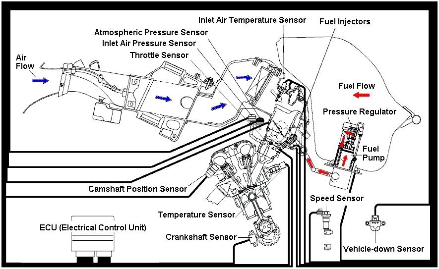
EFI – Electronic Fuel Injection pada Motor Oktober 24, 2007
trackback
 By Bengkelsepedamotor
Berbagai macam cara dan usaha yang dilakukan untuk mengurangi kadar gas buang beracun yang dihasilkan oleh mesin-mesin kendaraan bermotor seperti penggunaan BBM bebas timbal, penggunaan katalis pada saluran gas buang, dll.
Sebagaimana mesin 2 langkah yang harus digantikan oleh mesin 4 langkah, sistem karburasi manual akhirnya juga akan digantikan oleh sistem karburasi digital.
Sistem injeksi bahan bakar elektronik (karburasi digital) sudah mulai diterapkan pada mesin sepedamotor, perlahan tapi pasti akan menggantikan sistem yang sudah lama bertahan yaitu karburator (karburasi manual).
Karena mesin sepedamotor merupakan kombinasi reaksi kimia dan fisika untuk menghasilkan tenaga, maka kita kembali ke teori dasar kimia bahwa reaksi pembakaran BBM dengan O2 yang sempurna adalah:
14,7:1 = 14,7 bagian O2 (oksigen) berbanding 1 bagian BBM
Teori perbandingan berdasarkan berat jenis unsur, pada prakteknya perbandingan diatas (AFR – Air Fuel Ratio) diubah untuk menghasilkan tenaga yang lebih besar atau konsumsi BBM yang ekonomis.
Karburator juga mempunyai tujuan yang sama yaitu mencapai kondisi perbandingan sesuai teori kimia diatas namun dilakukan secara manual. Karburator cenderung diatur untuk kondisi rata-rata dimana sepedamotor digunakan sehingga hasilnya cenderung kearah campuran BBM yang lebih banyak dari kebutuhan mesin sesungguhnya.
Untuk EFI karena diatur secara digital maka setiap ada perubahan kondisi penggunaan sepedamotor ECU akan mengatur supaya kondisi AFR ideal tetap dapat dicapai.
Contohnya: Pada sistem Karburator ada perbedaan tenaga jika sepedamotor digunakan siang hari dibandingkan malam hari, hal ini karena kepadatan oksigen pada volume yang sama berbeda, singkatnya jumlah O2 berubah pasokkan BBM tetap (ukuran jet tidak berubah).
Hal ini tidak terjadi pada sistem EFI karena adanya sensor suhu udara (Inlet Air Temperature) maka saat kondisi kepadatan O2 berubah, pasokkan BBM pun disesuaikan (waktu buka injector ditambah atau dikurangi). Jadi sepedamotor yang menggunakan EFI digunakan siang atau malam tetap optimum alias tenaga tetap sama.
Perbedaan utama Karburator dibandingkan EFI adalah:
Karburator EFI
BBM dihisap oleh mesin BBM diinjeksikan/disemprotkan ke dalam mesin
Pengapian Terpisah Sistem Pengapian menyatu
Komponen-komponen dasar EFI
Setiap jenis atau model sepedamotor mempunyai desain masing-masing namun secara garis besar terdapat komponen-komponen berikut.
ECU – Electrical Control Unit
Pusat pengolah data kondisi penggunaan mesin, mendapat masukkan/input dari sensor-sensor mengolahnya kemudian memberi keluaran/output untuk saat dan jumlah injeksi, saat pengapian.
Fuel Pump
Menghasilkan tekanan BBM yang siap diinjeksikan.
Pressure Regulator
Mengatur kondisi tekanan BBM selalu tetap (55~60psi).
Temperature Sensor
Memberi masukan ke ECU kondisi suhu mesin, kondisi mesin dingin membutuhkan BBM lebih banyak.
Inlet Air Temperature Sensor
Memberi masukan ke ECU kondisi suhu udara yang akan masuk ke mesin, udara dingin O2 lebih padat, membutuhkan BBM lebih banyak.
Inlet Air Pressure Sensor
Memberi masukan ke ECU kondisi tekanan udara yang akan masuk ke mesin, udara bertekanan (pada tipe sepedamotor ini hulu saluran masuk ada diantara dua lampu depan) O2 lebih padat, membutuhkan BBM lebih banyak.
Atmospheric Pressure Sensor memberi masukan ke ECU kondisi tekanan udara lingkungan sekitar sepedamotor, pada dataran rendah (pantai) O2 lebih padat, membutuhkan BBM lebih banyak.
Crankshaft Sensor
Memberi masukan ke ECU posisi dan kecepatan putaran mesin, putaran tinggi membutuhkan buka INJECTOR yang lebih cepat.
Camshaft Sensor
Memberi masukan ke ECU posisi langkah mesin, hanya langkah hisap yang membutuhkan buka INJECTOR.
Throttle Sensor
Memberi masukan ke ECU posisi dan besarnya bukaan aliran udara, bukaan besar membutuhkan buka INJECTOR yang lebih lama.
Fuel Injector / Injector
Gerbang akhir dari BBM yang bertekanan, fungsi utama menyemprotkan BBM ke dalam mesin, membuka dan menutup berdasarkan perintah dari ECU.
Speed Sensor
Memberi masukan ke ECU kondisi kecepatan sepedamotor, memainkan gas di lampu merah dibanding kecepatan 90km/jam, buka INJECTOR berbeda.
Vehicle-down Sensor
Memberi masukan ke ECU kondisi sepedamotor, jika motor terjatuh dengan kondisi mesin hidup maka ECU akan menghentikan kerja FUEL PUMP, IGNITION, INJECTOR, untuk keamanan dan keselamatan.
Electronic Fuel Injection memang lebih unggul dibanding karburator, karena dapat menyesuaikan takaran BBM sesuai kebutuhan mesin standar.
ECU diprogram untuk kondisi mesin standar sesuai model sepedamotor, di dalam ECU terdapat tabel BBM yang akan dikirim melalui Injector sesuai kondisi mesin standar.
Jika ada perubahan dari kondisi standar misalnya filter udara diganti atau dilepas, walaupun ada pengukur tekanan udara (inlet air pressure sensor) pasokkan BBM hanya berubah sedikit, akhirnya sepedamotor akan berjalan tidak normal karena O2 terlalu banyak (lean mixture).
Tabel ECU standar biasanya tidak dapat dirubah, karena tujuan utama EFI adalah pengurangan kadar emisi gas buang beracun.
Untuk mesin modifikasi memerlukan modifikasi tabel dalam ECU, hal ini dapat dilakukan dengan:
1. Software yang dapat masuk ke dalam memory ECU – hanya dimiliki oleh ATPM atau dealer.
2. Piggyback alat tambahan diluar ECU – bekerja dengan cara memanipulasi sinyal yang dikirim ke Injector untuk membuka lebih lama.
3. Tukar ECU aftermarket yang dapat diprogram tabel memory-nya, sesuai modifikasi, sesuai kondisi sirkuit.
Salam,
bengkelsepedamotor
Catatan:
Tulisan diatas berdasarkan hasil teori dan praktek yang pernah saya lakukan dan merupakan pendapat pribadi, tidak ada kaitan atau mewakili salah satu produsen sepedamotor, maupun tempat bekerja saya saat ini.
Terbuka untuk ralat dan atau saran, CMIIW, Terimakasih.
Gambar diatas merupakan hasil penyederhanaan dari Service Manual 2004 Kawasaki ZX636-C1 (Ninja ZX-6R), TERIMAKASIH, jika ada pihak yang keberatan (e-mail ke: bengkel.motor@yahoo.co.id) karena masalah hak cipta, saya mohon maaf, dan gambar akan saya hilangkan.
Rabu, 17 November 2010
Motor masa Depan

Samson Motorworks mengklaim, bahwa mereka memiliki lisensi sepenuhnya atas teknologi pengembangan pesawat terbang roadable yang bernama SkyBike. SkyBike memiliki tiga roda dan dua kursi layaknya sepeda motor, dengan sayap utama teleskopis dan sebuah canard.
Digerakkan oleh baling-baling tunggal terselubung, dan didorong oleh sebuah mesin berputar, kendaraan ini akan mampu terbang dengan kecepatan 130 mph, meski saat ini belum dapat terbang.
Perusahaan ini sedang mengembangkan beberapa jenis model kendaraan. SkyBike adalah versi kitbuilt yang akan dikeluarkan lebih dulu, meskipun kapan tepatnya belum diketahui. SwitchBlade ini akan mendapat sertifikat dari Administrasi Penerbangan Federal Amerika Serikat (FAA). Prototipe SkyBike saat ini sedang dalam tahap pengerjaan di Swift Engineering , San Clemente, California.


SkyBike merupakan gagasan dari "Sam Bousfield". Dia mengklaim tata letak canard, dengan sayap utama di belakang, menunjang fungsi ganda. Untuk desain pada tempat yang aman dan mengurangi potensi terbalik saat berkendara, pusat berat badan dijaga dan tetap rendah ke belakang.
Memiliki sayap utama belakang dimana sebagian besar tempat daya angkut terletak pada mayoritas berat berada, memuji keamanan di darat maupun di udara. Selain itu, canard juga berfungsi sebagai penahan, dan mampu memberi perlindungan tambahan.

Perusahaan ini pun menawarkan berita berkala lewat email melalui situsnya bagi siapa saja yang ingin mengikuti perkembangan pembangunan proyek tersebut.

Jadi, apa pilihan kamu sekarang? Terrafugia atau SkyBike? Dua-duanya sama-sama kendaraan darat yang memiliki kemampuan untuk terbang, lho!
Sabtu, 13 November 2010
Rabu, 10 November 2010


Langganan:
Postingan (Atom)